 | Document # 2020 |
        |
Understanding Scanner Mechanics, Scan Modes and Interpolation(C) Mustek, 1996 All rights reserved. This document may not be reprinted,reproduced or distributed in anyway without the express written permissionof Mustek. |
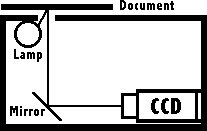
To get the most out of your new Mustek scanner, youwill need to understand some of the technical aspects of how it functions.Once you understand how the scanner works and what kind of data it sendsto your computer, you will have a good foundation for building additionalgraphic and desktop publishing skills upon. Scanner Mechanics – How They WorkFor simplicity, we will discuss flatbed scanners in this document; however,the basic principles apply to hand scanners and sheetfed scanners also. You begin by placing a document face down on the glass of your scannerand closing the lid. When you press the scan button, the scanhead insideyour scanner’s chassis begins to move. A flourescent light on the scanheadshines light upward onto your document or picture. This light is reflecteddownward and hits a mirror in the bottom of the scanhead which reflectsit towards a Charge Coupled Device (CCD) inside the scanner’s chassis.
Scanhead Of A Flatbed Scanner The CCD contains an array of photosensitive cells which read the intensityand/or color of the light that hits them. The CCD works with an analogto digital converter to convert the light to a level between 0 and 255(0 being darkest and 255 brightest). The CCD is what determines the Optical Resolution of your scanner. Themost common scanners have a 300 dot per inch CCD. This means that for everyinch of width in the image, the CCD can sample 300 individual dots of color.I will leave the detailed explanation of resolution issues to Document# 2050. Here we are only attempting to grasp the basic concepts. The scanner reads one line of data from your document at a time. Ifyou are scanning a 6" wide photograph at 300 DPI, the scanner willsend 6 x 300 or 1800 individual dots to the computer for the first lineof data. The motor will then move the scanhead to the next line. If yourphotograph is 4" tall, the scanner will produce 4 x 300, or 1200 individuallines when scanning at 300 DPI. Each of these dots may be a different colorand they are actually more like tiny squares than round dots. If you were to take a large number of tiny ceramic tiles made in a widevariety of colors, you could arrange them in such a way that they wouldshow a picture. When viewed from a distance, your tile mosaic would notlook jagged at all. But if you came up for a closer look, you would seejagged edges between various colors. The image produced by your scanneris basically a tile mosaic made of many very small square dots. Using theexample above of a 4 x 6 inch photograph, the scanned image would consistof 2,160,000 dots. This is the product of 1200 x 1800 which were calculatedin the above paragraph. Your scanned image does not appear jagged becausethe dots are very small. Below are images of a postage stamp that was scanned at 72 DPI. Thepicture on the left is the entire stamp. The picture on the right is anenlarged segment of the stamp. It has been magnified five times to showthe mosaic dot pattern detected by the scanner. Notice that the stamp appearson your screen actual size. This is because computer monitors have a resolutionof 72 DPI. (Hint: Scan at 72 DPI for Web Pages. If you scan higher thanabout 100 DPI, your images may not fit on your Web Page unless, of course,they’re as small as postage stamps.) |
|
|
Scanned at 72 DPI Shown Actual Size | Enlarged Five Times Note Mosaic Pattern |
These tiny squares of color are the data that a scannersends to the computer. Once you get the dots into your computer, differentsoftware applications handle them in different ways. See Document# 2030, Understanding File Formats, for more information about howdifferent programs use this data. Scan ModesComputers represent pictures in a variety of ways. The four methodsthat are most common are line art, halftone, grayscale, and color. Beloware examples of each: |
|
|
|
|
1-Bit Line Art | 1-Bit Half Tone | 8-Bit Greyscale | 24-Bit Color |
| Line Art Line art is the smallest of all the image formats. Since only blackand white information is stored, the computer represents black with a 1and white with a 0. It only takes 1-bit of data to store each dot of ablack and white scanned image. The diagram of a flatbed scanner mechanism near the top of this pagewas scanned in the line art mode. Line art is most useful when scanningtext or line drawing. Pictures do not scan well in line art mode. Halftone While computers can store and show gray-scale images, most printersare unable to print different shades of gray. They use a trick called halftoning.Halftones use patterns of dots to fool the eye into believing it is seeinggray-scale information. For example, the patterns below represent a totallywhite dot, a 25% gray dot and a 50% gray dot.
Grayscale Grayscale images are the simplest of images for the computer to store.Humans can perceive about 255 different shades of gray. Computers representgrayscale information by storing a number from 0 to 255 in a single byte.When you view a grayscale image, it is equivalent to seeing a black andwhite photograph.
Color Color images are the largest and most complex images to store. TVs andcomputer monitors mix the colors red, green, and blue to display all thecolors visible to the human eye. If you were to look at your computer screenright now through a high powered magnifying glass, you would see that thewhite background of this page is actually made up of high intensity red,green and blue dots arranged like the diagram below. A pixel is a groupof three dots, one of each color. Because the dots are very tiny, youreyes blend them together and you see white.
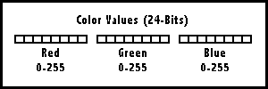
The monitor’s internal electronics can vary the intensity of each colordot to 256 different levels of intensity. At the 0 intensity level, thedots are completely off and the screen appears black. If the red and greenintensity is 0 and the blue intensity is 255, you see a rich blue colorlike the one above. By varying the intensity of each color dot between0and 255, there are 16.77 million different combinations. Each combinationappears as a different color. If the intensity of each dot is set to anequal value, say 128, the monitor will appear as a grey shade. 128 wouldbe the level of 50% grey. This is why there are only 256 greyshades whenscanning in greyscale mode. Computers use 8-bits (1 byte) to represent each of the color components(red, green, and blue). With 8-bits for each of the three colors thereare a total of 24-bits to represent the entire color spectrum.
How to Determine File Size If you’re curious how to determine how large a scanned image File Size = (Resolution x Horizontal Size) x (Resolution x VerticalSize) x Scan Mode Where Scan Mode = 1/8 for line art and halftone, 1 for grayscale and3 for color. Here are the file sizes for a 4" x 4" photo at various scanmodes and resolutions. Notice that the greyscale files are 8 times as largeas the lineart files. The color files are 24 times as large as the lineartfiles and 3 times as large as the greyscale files. |
4" x 4" image | 100 DPI | 150 DPI | 300 DPI | 600 DPI |
Line Art/Halftone | 19.5 Kb | 44 Kb | 175 Kb | 703 Kb |
Grayscale | 156 Kb | 352 Kb | 1.37 Mb | 5.5 Mb |
Color | 469 Kb | 1 Mb | 4.12 Mb | 16.5 Mb |
InterpolationThe resolution of a scanner is determined by the Optical Resolutionof the CCD and the Stepping Speed of the scanner’s motor. A 300 x 600 DPI scannerhas a 300 dot per inch CCD and a motor that goes slow enough to scan 600lines per inch as it travels the length of the bed. If you scan at 300DPI on such a scanner, the motor runs twice as fast as it does when scanningat 600 DPI. If you scan at 600 DPI on such a model, the motor runs slowerand the scanner’s hardware interpolates the horizontal data from 300 upto 600 DPI. Basically, an integrated circuit chip in the scanner generatesnew data where there is none through an algorithm by averaging the colorof adjacent dots and creating a new dot between them of the average color.This is Hardware Interpolation and it allows a 300 x 600 DPI scanner toproduce a 600 x 600 DPI image. Software Interpolation can increase the resolution even more than HardwareInterpolation. Software Interpolation is performed by the Twain driverwithin the Computer’s CPU. This type of interpolation is quite misleading.It does not create sharper images. Image quality and sharpness is alwayslimited by Optical Resolution. Software Interpolation merely increasesthe amount of data in a scanned image. It is roughly equivalent to scalingan image to make it larger. The only good reason to scan at very high resolutions, such as 4800DPI, is when you need to enlarge an image dramatically. If the postagestamp used above were scanned at 4800 DPI, the file size would be 19.1MB.This would increase to 76.4 MB at 9600 DPI. If you were even able to scanan 8.5" x 11" page in color at 9600 DPI, you would need a 12Gigabyte hard drive to store the resulting file! (Obviously, your computerwould crash if you tried this) |
| Mustek and the Mustek logo are trademarks and registered trademarksof Mustek, Incorporated. Any use without the express written permissionof Mustek is forbidden. Other company and product names may be trademarksor registered trademarks. |